
KWD Industrial Couplings
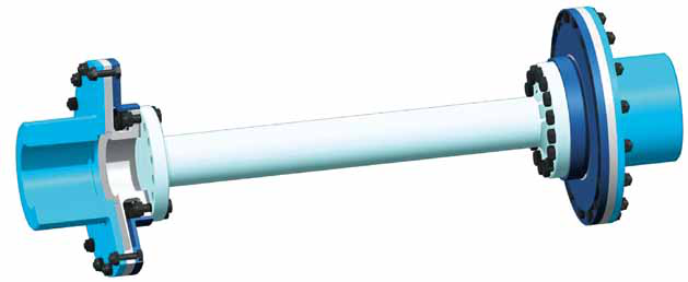
Diaphragm Couplings (MEM)
Diaphragm couplings are torsionally stiff, bending flexible couplings for backlash-free transmission of torque. They accommodate angular misalignment and axial displacement; in double cardanic design, parallel offset can also be accommodated. Provided the shaft misalignments are kept within the specified limits, the diaphragm coupling is designed for infinite life and is wear-free and maintenance-free — the preferred technical solution for critical applications with high torques and high speeds.
For more than two decades, KWD Kupplungswerk Dresden has supplied diaphragm couplings in varying designs for a wide variety of applications. The diaphragm is dimensioned project-specifically with the help of proprietary selection software and then FEA-optimised. All couplings are manufactured on state-of-the-art machines in our factory in Dresden, subsequently assembled and, if required, fully tested before delivery.
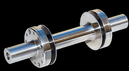
Design types
• Single diaphragm coupling — for single bearing motors and generators
• Double diaphragm coupling — according to API 671, for turbo compressors
• Electron beam welded double diaphragm coupling with Hirth serration — for railway traction drives
• Electron beam welded quadruple diaphragm coupling — for gas turbines
• Electron beam welded quadruple diaphragm coupling — for high-speed drives (up to 95,000 min⁻¹)
• Quadruple diaphragm coupling with overload protection — for railway traction drives
• Insertable, torsionally flexible double diaphragm coupling — for railway traction drives
Basic design
Each diaphragm coupling consists of the flexible diaphragm and the two interfaces at the inner and outer diameter; the connection interfaces can be designed as internal or external hubs or as flanges. The diaphragm can be used in a single arrangement; for larger angular displacements a design with several diaphragms should be selected, and at least two diaphragms are necessary to accommodate parallel offset. By varying the spacer length the coupling can be fitted to the required distance between shaft ends (DBSE); the diaphragm can either be bolted to the spacer or welded by electron beam. Suitably selecting diaphragm diameter, contour and spacer length optimises elasticity, reactionary loads and displacement capability for the specific application.
Typical applications
Gas and steam turbines, pumps, compressors, blowers, generators, test stands, marine drives, railway traction drives, construction machinery drives, single bearing motors and generators.
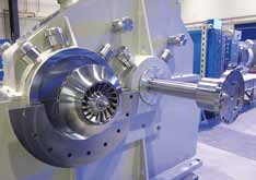
Technical features
• High power density, very high balance quality, very high torques and speeds
• Very large temperature range; very low influence of temperature and service life on the elastic characteristics
• Lubrication-free; definable reactionary loads and restoring moments
• Low noise emission, low heat development, corrosion resistant; low overhung moment, low-windage design
• Rotor dynamic characteristics can be adapted to the requirements of the drive train
• Constant stress distribution through contoured diaphragm
• Limited number of components and few interface connections reduce the potential for error to a minimum
Special designs
• Design according to API 610 and API 671 (ISO 10441)
• Use in explosive environments (according to ATEX Directive 94/9/EC)
• Limited end float design, integrated overload protection, electrical isolation
• Design for retention of the spacer; higher balancing quality and repeatability
• Vibration-optimised design according to customer requirements
Value for the operator
• Maximum safety and availability; maximum service life provided shaft misalignments are within specified limits
• Very low influence of service life or temperature on the dynamic properties
• Coupling removal and reinstallation without shifting connected equipment
Compared with our disc couplings (GMK series): dynamically more stable as a generally stiffer coupling type and higher speeds reachable; no fretting corrosion and no wear; fewer parts and a better power-to-weight ratio.